
Since three month, I spend some time in the OpenAPS community. Of course I build some rigs and I try to find the optimal configuration for me at the moment. My design goals are clear:
- I want a super small rig, to carry it around all the time.
- It should run for at least one working day (10 hours).
- It should be super cheap to build, since it is a commodity item and may get damaged regularly.
- I don’t want to spend to much time to care about software issues.
Thankfully, the OpenAPS community has nearly the same design goals, and thus, there is lot’s of soft- and hardware around the RaspberryPi Zero. The current state-of-the-art solution is the Pi0 together with a communication board called 900MHZ Explorer HAT. It offers a radio chip, a step-up converter to use 1S Li-Po batteries to power the pi, a charging circuit to charge the 1S Li-Po, some LEDs and a display. It works quite well, but let’s face it: I hate it! I have lots of complains about that board, but that’s a topic for a different post. The important points are:
- It’s way to expensive! (~180 EUR inkl. tax, toll and shipping).
- I don’t need the display.
So .. typical (maybe German) reaction from my side: „Hold my beer for a moment, I can do that!“. I thought a bit, how to make it super small and easy to build at the same time (since I have no clue about electrical engineering). My solution was to build a daughter board, holding a RF module, a chip antenna, the Pi0, a buck-boost regulator and a ADC for measuring battery voltage. I also added some buttons and some LEDs just in case …
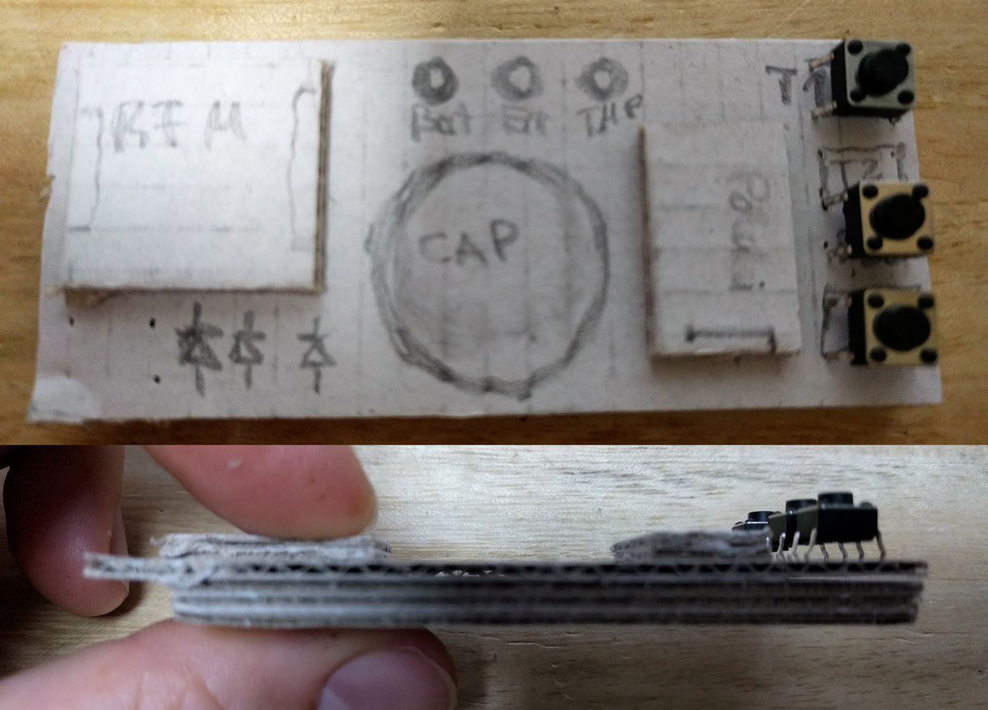
After some work making a schematic and a board design, I simply ordered everything and tired to build it up. The board came as 3 in 1 panels, so I had so separate them first. The quality looks decent and it seems to have enough space for all components.


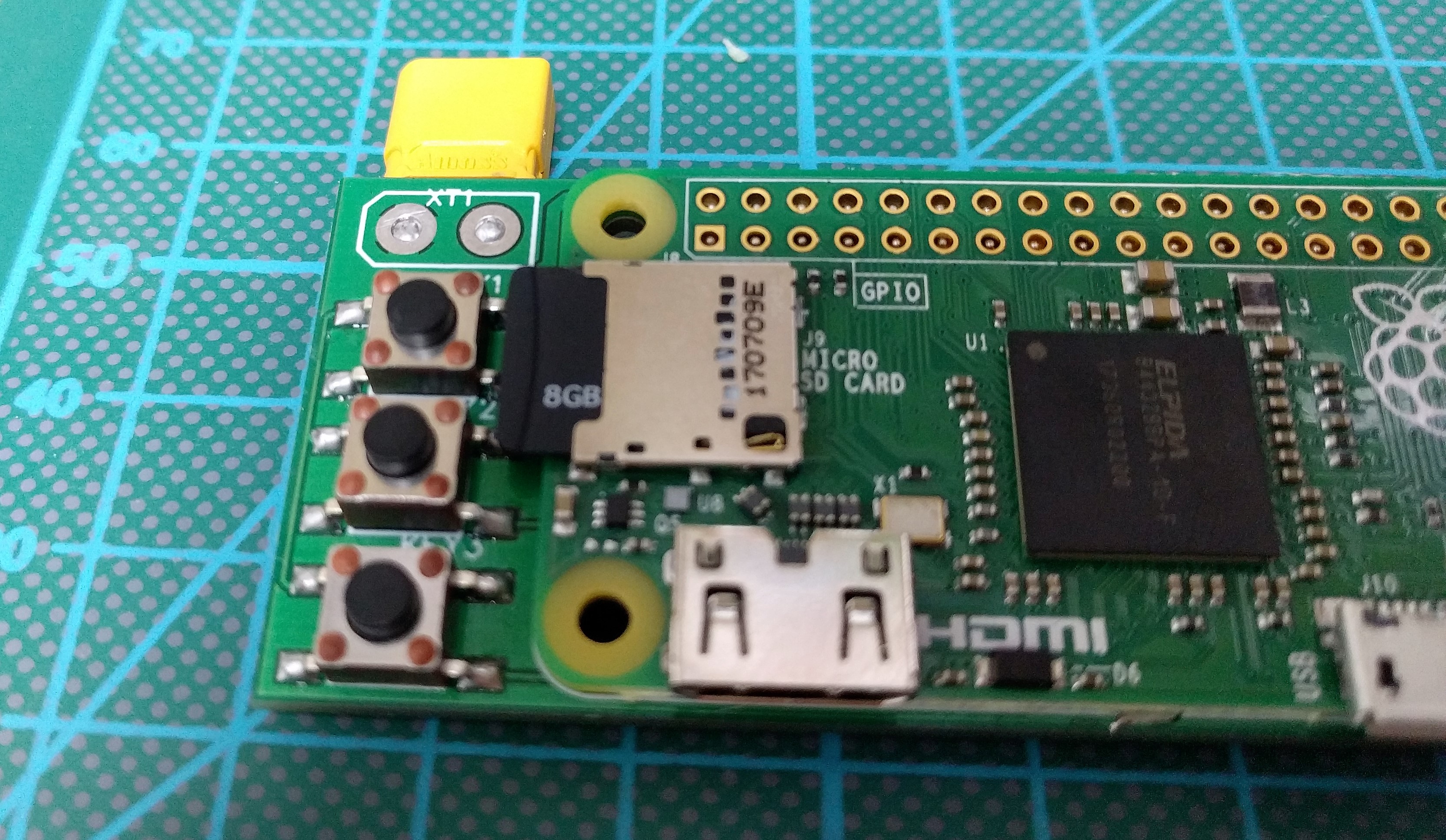
Motivated from this first success I started soldering. As one of my design goals was easy to build, I used 1206 SMD components, since they are pretty easy to solder but keep the design small. As power plug I used a XT40 connector, since I have a lot of 2S batteries from my drones (caution: the voltage regulator destroys itself and every other component on the board including the Pi0 if you put more voltage than 11V). The RFM69 is place able as SMD component out of the box. For the voltage regulator I had to cut the board a bit, to be able to solder the through hole connections to my daughter board, but wasn’t any of an issue.


BTW: As minimal version, it’s enough to solder the voltage regulator, the radio board and a power plug along with some pin headers for the PI0. As Antenna a piece of wire with a length of 86 mm (for 868 MHz) is good enough.
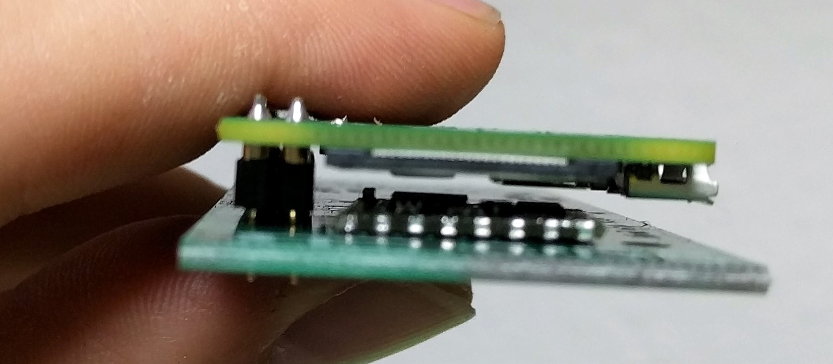
As always in my hardware projects, I had some issues while placing the components. I figured, the SD-card slot is unreachable if I solder the buttons and the Pi und the bottom layer.
To fix this, I put the Pi0 on the upper layer. The result isn’t as thin as it was supposed to be, but still ok (and still thinner as the Explorer HAT 😀 ). For now, it’s good enough as development platform and for testing. When the main problems are solved and the software is ported, maybe I’ll update the design to match the original design goals.
I put together some affiliate links if you want to gather the parts at Amazon:
One word on software support: Since the OpenAPS usually uses a different (and lot more expensive) radio device, the RFM69 is not supported out of the box. At the current time, it’s possible to run this board with the oref0 version 0.7.0-dev, if the corresponding communication programs (programmed in GO-lang) are compiled with the tag „-tags rfm69“. More information about this is shown on github. I’ll work on this and write an update when the software is full compatible.
PS: I have some left over boards, which I’ll give away for free (except shipping). Just ask if you like to have one 🙂

Guten Tag,
ich hätte Interesse an einem Modul Board (so wie Explorer Hat) von Ihnen.Kann ich Sie privat kontaktieren?
Liebe Grüße
Hi Jens. Hast du schon mal ein Edison rig gebaut? die sind etwa so gross (klein), und eine 2500 mAh LiPo Batterie reicht normalerweise den ganzen Tag.
Ah – witzig: Halt mal mein Bier! Trust me … dem Ingenieur ist nichts zu …
KJ – Dipl-In in Seattle
Moin! Nein da Edisons nicht mehr hergestellt werden kam ich damals nicht zu einem vernünftigen Preis an einen ran. Ich denke aber es ist generell keine gute Idee jetzt noch auf Edison zu setzten da die Software nach und nach auf Pi optimiert wird…
Leider werden die Intel Edison nicht mehr produziert. Deshalb sind die Preise extrem gestiegeb, weil die Nachfrage in der Comunity hoch ist. Finde ich daher keine sehr nachhaltige Lösung 😦
Hi Jens,
bin aus zweierlei Gruenden auf Deine Seite gestossen und waere unter anderem auch an einem OpenAPS rig interessiert wenn Du noch eins ubrig hast…
So oder so, bitte schreib mir privat !
Danke vielmals !